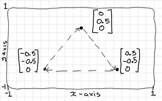
This shape might have a vertex buffer: {0, 0.5, 0, 0.5, -0.5, 0, -0.5, -0.5, 0}
A vertex buffer object (VBO) is nothing fancy - it's just an array of data (usually floats). We already had a look at the most basic use of vertex buffer objects in the Hello Triangle tutorial. We know that we can describe a mesh in an array of floats; {x,y,z,x,y,z..x,y,z}. And we also know that we need to use a Vertex Array Object to tell OpenGL that the array is divided into variables of 3 floats each.
The key idea of VBOs is this: in the old, "immediate-mode" days of OpenGL, before VBOs, we would define the vertex data in main memory (RAM), and copy them one-by-one each time that we draw. With VBOs, we copy the whole lot into a buffer before drawing starts, and this sits on the graphics hardware memory instead. This is much more efficient for drawing because, although the bus between the CPU and the GPU is very wide, a bottleneck for drawing performance is created when drawing operations stall to send OpenGL commands from the CPU to the GPU. To avoid this we try to keep as much data and processing on the graphics hardware as we can.
A VBO is not an "object" in the object-oriented programming sense, it is a simple array of data. OpenGL has several other types of data that it refers to as singular "buffer objects". I gather that the term "object" here implies that OpenGL gives us a handle or identifier number to the whole buffer to interact with, rather than a traditional address to the first element in the buffer. I should probably refer to these as "buffer objects" everywhere, but I'm not one for pedantry, so I use "vertex buffer", and "vertex buffer object" interchangeably in the text.
We will look at managing vertex buffers in a little bit more depth. We will need this for enabling lighting and texturing effects later. We will break down the interface, and visualise how interpolation between the vertex shader and the fragment shader works.
Write up a working demo that renders a triangle. You might use Hello Triangle if you haven't got one already. Then we can play with the glDrawArrays() function. So far, we have just looked at rendering triangles from sets of 3 points, but you can actually render in several different modes:
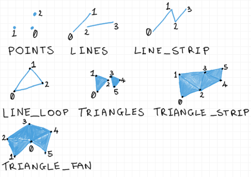
Try changing your GL_TRIANGLES parameter. You can see that points and lines are going to be useful for drawing thing like charts or outlines. Triangle strip is a slightly more efficient method for drawing ribbon-like shapes. You can actually change the size of the points in the vertex shader using the gl_PointSize built-in variable, so they are quite versatile. Lines no longer have very good supporting functions, as hardware and drivers have become triangle based, so they're not reliable. These days you would likely construct lines out of triangles.
All of my students tried to make a wire-frame rendering mode so I thought I'd point this out here - it's much easier to use the built-in function than to attempt to draw everything with GL_LINES. Call glPolygonMode(GL_FRONT, GL_LINE); before rendering.
We can store more than just 3D points in a vertex buffer. Common uses also include; 2D texture coordinates that describe how to fit an image to a surface, and 3D normals that describe which way a surface is facing so that we can calculate lighting. So it's quite likely that most of your objects will have 2 or 3 vertex buffers each.
You can use vertex buffers to hold any data that you like; the key thing is that the data is retrieved once per vertex. If you tell OpenGL to draw an array of 3 points, using a given vertex array object, then it is going to launch 3 vertex shaders in parallel, and each vertex shader will get a one variable from each of the attached arrays; the first vertex shader will get the first 3D point, 2D texture coordinate, and 3D normal, the second vertex shader will get the second 3D point, 2D texture coordinate, and 3D normal, and so on, where the number of variables, and size of each variable is laid out in the vertex array object.
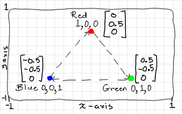
Vertex colours are very seldom used in practise, but most modern GL tutorials will get you to create a buffer of colours as a second vertex buffer. Why? Because it's easy to visualise how interpolation works with colours. So let's do that - our colours will be similar to 3D points - except they will have r,g,b values of 0.0 to 1.0 instead of positions. Let's use our triangle of points again (as pictured above), and make a buffer of colours with one vertex completely blue, one completely red, and one completely green.
float points[] = {
   0.0f,  0.5f,  0.0f,
   0.5f, -0.5f,  0.0f,
  -0.5f, -0.5f,  0.0f
};
float colours[] = {
  1.0f, 0.0f,  0.0f,
  0.0f, 1.0f,  0.0f,
  0.0f, 0.0f,  1.0f
};
You can see that the colour values are going to correspond to the position values. Example:
Okay, now for each one we can create a GL vertex buffer object, bind it in the state machine, and copy the array of values into it. Both colours, and points have 9 components each (3 vertices with 3 components per vertex). We set up one buffer after the other, because the state machine can only have 1 buffer bound at a time.
GLuint points_vbo = 0;
glGenBuffers(1, &points_vbo);
glBindBuffer(GL_ARRAY_BUFFER, points_vbo);
glBufferData(GL_ARRAY_BUFFER, 9 * sizeof(float), points, GL_STATIC_DRAW);
GLuint colours_vbo = 0;
glGenBuffers(1, &colours_vbo);
glBindBuffer(GL_ARRAY_BUFFER, colours_vbo);
glBufferData(GL_ARRAY_BUFFER, 9 * sizeof(float), colours, GL_STATIC_DRAW);
Our object now consists of 2 vertex buffers, which will be input "attribute" variables to our vertex shader. We set up the layout of both of these with a single vertex array object - the VAO represents our complete object, so we no longer need to keep track of the individual VBOs.
Note that we have to bind each VBO before calling glVertexAttribPointer(), which describes the layout of each buffer to the VAO.
The first parameter of glVertexAttribPointer() asks for an index. This is going to map to the indices in our vertex shader, so we need to give each attribute here a unique index. I will give my points index 0, and the colours index 1. We will make these match up to the variables in our vertex shader later. If you accidentally leave both indices at 0 (easy enough to do when copy-pasting code), then your colours will be read from the position values so x→red y→green and z→blue.
Both buffers contain arrays of floating point values, hence GL_FLOAT, and each variable has 3 components each, hence the 3 in the second parameter. If you accidentally get this parameter wrong (quite a common mistake), then the vertex shaders will be be given variables made from the wrong components (e.g. position x,y,z gets values read from a y,z,x).
GLuint vao = 0;
glGenVertexArrays(1, &vao);
glBindVertexArray(vao);
glBindBuffer(GL_ARRAY_BUFFER, points_vbo);
glVertexAttribPointer(0, 3, GL_FLOAT, GL_FALSE, 0, NULL);
glBindBuffer(GL_ARRAY_BUFFER, colours_vbo);
glVertexAttribPointer(1, 3, GL_FLOAT, GL_FALSE, 0, NULL);
That is the mesh side taken care of - you only need to do this part once, when creating the object. There is no need to repeat this code inside the rendering loop. Just keep track of the VAO index for each type of mesh that you create.
Okay, so we created a vertex array object, and described 2 attribute "pointers" within it. Unfortunately, attributes are disabled by default in OpenGL 4. We need to explicitly enable them too. This is easy to get wrong or overlook, and is not well explained in the documentation. We use a function called glEnableVertexAttribArray() to enable each one. This function only affects the currently bound vertex array object. This means that when we do this now, it will only affect our attributes, above. We will need to bind every new vertex array and repeat this procedure for those too.
glEnableVertexAttribArray(0);
glEnableVertexAttribArray(1);
We are using 2 attributes (points and colours), and we know that these are numbered 0 (points), and 1 (colours); matching the numbers we gave when setting up the vertex attribute pointers, earlier.
If you forget to enable an attribute, the shader won't know where to read the data from and you'll get weird results e.g. black colours. I believe attribute 0 is enabled by default, but the second attribute that we added will not be. This process is a bit excessive, and I feel should really be handled differently by OpenGL, but in this version we still need to do it.
Now, we want our shader to render using the second vertex buffer, so we need to add a second attribute to the top of the vertex shader. We are going to add the OpenGL 4 layout prefix to each attribute. This lets us manually specify a location for each attribute - and we are going to match this up to the index that we gave each one in glVertexAttribPointer. If you don't specify a location, the shader programme linker will automatically assign one. You can query this, which we did in Shaders, but I prefer to specify it manually so I can see the values as I write.
layout(location = 0) in vec3 vertex_position;
layout(location = 1) in vec3 vertex_colour;

out vec3 colour;

void main() {
  colour = vertex_colour;
  gl_Position = vec4(vertex_position, 1.0);
}
Now, the other interesting change here is that I took the vertex_colour input attribute and gave it to an output variable, which I called colour. This is where it gets interesting. It has no effect on our vertex shader, but outputs it to the next stage in the programmable hardware pipeline. In our case - the fragment shader.
If you want your GLSL code to be compatible with OpenGL 3.2, for example, then you can't use the newer layout keyword. You can achieve the exact same effect by telling the shader's linker which variable should have which location. Right after compiling but before linking, you can call glBindAttribLocation() to do this:
...
glCompileShader(my_vertex_shader);
glCompileShader(my_fragment_shader);
glAttachShader(shader_programme, my_fragment_shader);
glAttachShader(shader_programme, my_vertex_shader);

// insert location binding code here
glBindAttribLocation(shader_programme, 0, "vertex_position");
glBindAttribLocation(shader_programme, 1, "vertex_colour");

glLinkProgram(shader_programme);
...
You don't need to use both methods - one or the other is fine. The third option is to let the linker decide which location to give each input variable, and then you use a value returned by glGetAttribLocation() for the first parameter of calls to glVertexAttribPointer().
We can rewrite the fragment shader to use our new colour variable as an input, which will colour each fragment directly. Note that we add an in prefix to retrieve a variable from a previous stage. This in/out convention is a little different to how other OpenGL versions work. Our output fragment colour needs to be r,g,b,a (4 components) so we can just add a 1 to the end of our 3-component colour by casting it as a vec4.
in vec3 colour;
out vec4 frag_colour;

void main() {
  frag_colour = vec4(colour, 1.0);
}
That's it! Our drawing loop should look the same as with the Hello Triangle demo. Note that it's just the single VAO that needs to be bound for drawing; older OpenGL versions will have you bind both arrays, but not OpenGL 4:
while(!glfwWindowShouldClose(window)) {
  glClear(GL_COLOR_BUFFER_BIT | GL_DEPTH_BUFFER_BIT);
  glUseProgram(shader_programme);
  glBindVertexArray(vao);
  glDrawArrays(GL_TRIANGLES, 0, 3);
  glfwPollEvents();
  glfwSwapBuffers(window);
  if(glfwGetKey(window, GLFW_KEY_ESCAPE)) {
    glfwSetWindowShouldClose(window, 1);
  }
}
You can test that it works now!
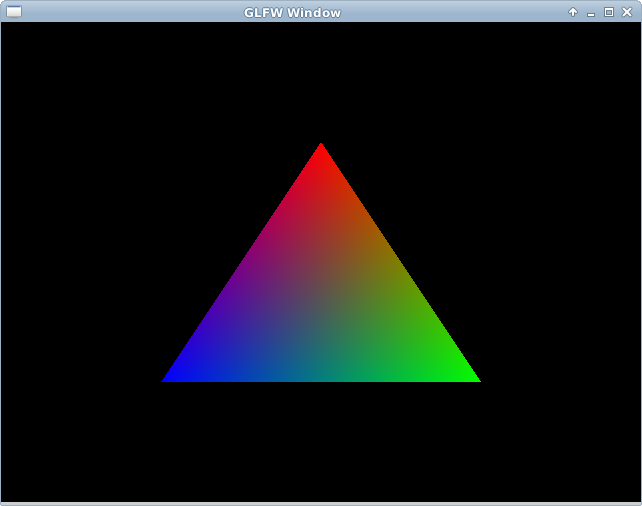
Now, remember, our triangle has only 3 vertices, but 1 fragment for every pixel-sized area of the surface. This means that we have 3 colour outputs from vertex shaders, and perhaps 100 colour inputs to each fragment shader. How does this work?
The answer is that each fragment shader gets an interpolated colour based on its position on the surface. The fragment exactly on the red corner of the triangle will be completely red (1.0, 0.0, 0.0). A fragment exactly half-way between the blue and red vertices, along the edge of the triangle, will be purple; half red, half blue, and no green: (0.5, 0.0, 0.5). A fragment exactly in the middle of the triangle will be an equal mixture of all 3 colours; (0.3333, 0.3333, 0.333).
Keep in mind that this will happen with any other vertex buffer attributes that you send to the fragment shader; normals will be interpolated, and texture coordinates will be interpolated to each fragment. This is really handy, and we will exploit it for lots of interesting per-pixel effects. But it's quite common to misunderstand this when getting started with shaders - vertex shader outputs are not sending a constant variable from a vertex shader to all fragment shaders. We use uniform variables for that.
The last thing that you should know about is a built-in rendering optimisation called back-face culling. This gives a hint to GL so that it can throw away the hidden "back" or inside faces of a mesh. This should remove half of the vertex shaders, and half of the fragment shader instances from the GPU - allowing you to render things twice as large in the same time. It's not appropriate all of the time - you might want our 2D triangle to spin and show both sides.
The only things that you need specify are if clock-wise vertex "winding" order means the front, or the back of each face, and set the GL state to enable culling of that side. Our triangle, you can see, is given in clock-wise order. Most mesh formats actually go the other way, so it pays to test this before wondering why a mesh isn't showing up at all!
glEnable(GL_CULL_FACE); // cull face
glCullFace(GL_BACK); // cull back face
glFrontFace(GL_CW); // GL_CCW for counter clock-wise
Try switching to counter clock-wise to make sure that the triangle disappears. If you were to rotate it around now you'd see the other side was visible. As with other GL states, this culling is enabled globally, in the state machine, you can enable and disable it between calls to glDrawArrays so that some objects are double-sided, and some are single-sided, etc. Keep in mind which winding order you are making new shapes in..