My converter successfully converted an IFC mesh that my viewer could draw in OpenGL 4, but some bits were missing.
I did a bit of poking around to find out why my IFC-to-custom-format conversion was missing triangles. I suspected that some were still quads. I imported the IFC into Blender, triangulated it, and exported in Wavefront .obj and I still had the same problem. Curious!
I used my converter's post-processing tools to clean up the mesh, but this didn't work very well, and introduced some additional errors. On closer investigation the files were fragmented into a very high number of separate 'sub-meshes'. These didn't seem to follow any sensible order; one would presume that the cars would be a sub-mesh, the roof another, etc. I suspect that the IFC 'classes' (templates) are represented as separate 'objects' in 3d graphics jargon (an object is a sub-mesh). Probably the converter couldn't deal with merging hundreds and hundreds of objects together. It's absolutely not efficient to separate a mesh into sub-meshes for drawing because it doesn't make use of the parallelism of modern graphics hardware. I was only using one drawing operation - one sub-mesh drawn, so it was more than likely missing some of the extra pieces if they weren't religiously put into the same hierarchy of IFC classes.
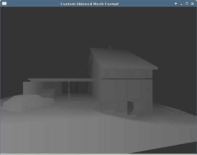
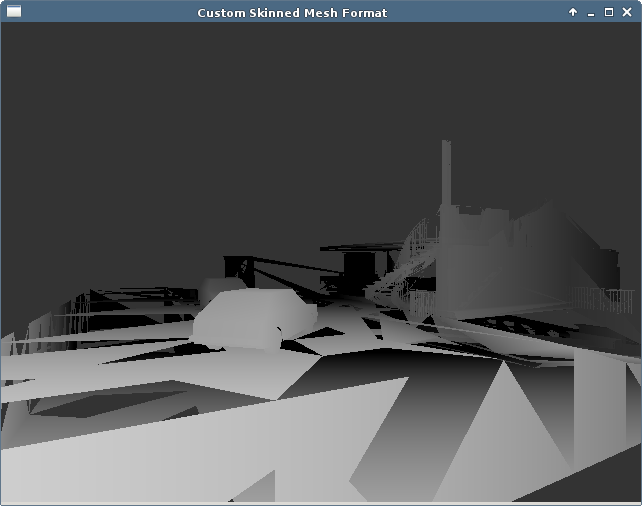
I imported the IFC into Blender and manually 'cleaned up' the mesh. There were thousands of repeated (redundant) vertices that I stripped away. I also 'joined' all of the objects/classes/sub-meshes into a single mesh with no hierarchy anything. I forcibly triangulated the entire mesh, recalculated the normals to all face outwards, and applied various small optimisations. This seemed to fix the main problem, as pictured above. There are some holes in it though (between floors, for example). Either some objects were left out, or the polygons are in a reverse order to the rest, and the viewer thinks that they are facing the other way, and would be visible from inside the house.

I disabled 'back-face culling' so that forward and backward-facing polygons were all drawn. This is very in-efficient to draw, but shows that yes, indeed, some of the polygons from the IFC are defined in an inconsistent order to the rest! This could be because some of the non-triangular polygons were incorrectly triangulated, but I doubt it.
| File Format | File Size (kB) |
| .ifc | 14600 |
| .obj | 1400 |
| .apg | 3400 |
The above table gives a comparison of file sizes for the same sample IFC mesh that only contains geometry for drawing. Firstly, the original file in IFC format was a gigantic 14.6 MB. This is really too large to use as an interchange format over the web. The exact same geometry in a face-indexed Wavefront .obj file is only 1.4 MB, and in my custom non-index format it is still only 3.4 MB. Why is the IFC file an order of magnitude larger? My own format is already excessively verbose for the purpose of readability and debugging, and has no optimisation at all.
I did a quick analysis of the test file. A sample of the critical part of the file is above. Although it is better suited for C-style fscanf parsing than XML-based formats, it still has some irritations around variable numbers of, or optional attributes. Ignoring that small issue, some more important observations of weak points in the format:
Basically, the main failing is that the amount of bytes used to represent a single data point is far too high. In IFC a point itself (just the XYZ value) occupies about 50 bytes of data. I would argue that the precision used is probably too high, far beyond the actual accuracy of the data, which is misleading. We want to use float to represent data for drawing, and this can only be guaranteed to support 8 s.f. Do we really have measurements of the building down to 10^-17 of a meter? I don't think so! The wood used in the building will warp above the mm range. These values could probably be about 20 bytes. Regardless, the main problem is that every data point comes with another 90 bytes of data saying that it is a data point. This could easily be addressed by having a single line appear before all the points that says something to the tune of "2000 3d points follow this line".
Now, this is only for a trivial example file. For a larger building that also includes other types of system that are not for graphical display we have something that takes several minutes to parse, and is far too big to be requested over the web (my primary use-case). I'm disappointed that it's still too intricate to reliably build an automatic converter for. I still had to do a significant amount of by-eye manual clean-up before it was ready for conversion to another format. My gut feeling is that using a complex format like this that allows bad geometric design is not a good idea. It's not good for interchange over the web, or for any sort of drawing, and I don't see good reasons for this - it's just not efficiently designed. I think it would be better to get the users of CAD design software to understand why a mesh should be designed a certain way for efficient rendering. It's no longer really appropriate for a designer to not know how modern 3d graphics hardware works when there are so many interesting, and incredibly useful run-on applications of visualising these building plans in 3d.